GraspIO CloudIO
The SMART development add-on board for the Raspberry Pi
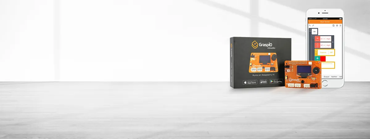
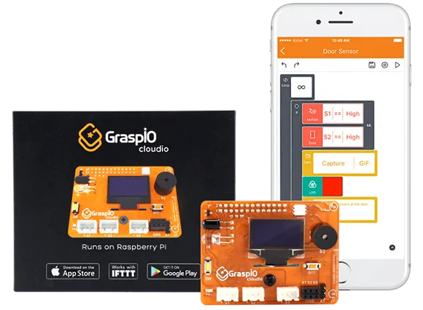
The GraspIO CloudIO SMART development board is an add-on board for the Raspberry Pi. It features a number of onboard sensors, as well as a small OLED display, RGB LED, buzzer, tactile switch, mini servo port, and a number of input and output ports for external sensors and digital outputs.

Although the CloudIO board has a 26 pin GPIO socket, it is compatible with all Raspberry Pi models; including those with the 40 pin GPIO header.
Programming of the CloudIO is done by means of a block based 'drag and drop' programming app which is available for both Android and iOS.
Set up of the CloudIO is very straightforward using either a pre-programmed SD card, or by means of a software image which can be downloaded from the GraspIO website. As with most Raspberry Pi images, the downloaded software image can be loaded onto a microSD card using an image burning utility such as Etcher.

Once the SD card has been prepared, it is simply a matter of attaching the CloudIO board to the Raspberry Pi, inserting the SD card into the Raspberry Pi, and powering up the Pi; the Pi doesn't even need to be attached to a monitor, keyboard or mouse.
Having powered up the Raspberry Pi, the next step is to download the GraspIO App onto a phone or tablet, and run the App. This App walks you through the steps required to attach the Pi to a wireless network. One of these steps does however require that the phone or tablet running the GraspIO App be connected to the Raspberry Pi using a USB cable, so you will need to ensure that you've got one of these to hand.


Once connected to the wireless network, the Raspberry Pi will reboot, and the USB cable can be disconnected.
Having set up the Raspberry Pi and CloudIO board, it is all ready to be programmed. This programming is done by means of blocks which can be dragged and dropped onto a palette. The various blocks are organised in groups based on the type of functionality provided; for example, control, input, output, etc. There are a number of simple example projects which can be run to demonstrate the various capabilities of the CloudIO board.


We thought we'd check out some of the basic functionality of the board by trying out a simple project of our own. We happened to have a servo motor available, and with the CloudIO board having a servo interface and a light sensor, we were inspired to create our very own CloudIOmeter; to tell us whether or not it is cloudy.
A sheet of A4 with a printed cloud and sun icon was folded and stuck on to the rotor of the servo motor.


The servo motor connects directly to 3 pin servo connector on the CloudIO board. The only thing to be careful of is that the connector is connected the right way round. The +ve pin on the board should line up with the red cable of the servo motor, and the –ve pin with the black cable. The third pin is the data cable; which for our servo motor is white.
The program for our project is really simple, and consists of an infinite loop with a delay of one second between each iteration of the loop. Inside the loop, the light level is sampled and compared to a defined value (we used the value 250). If the light level is below this value, a cloud icon is displayed on the OLED display, and the servo is rotated to an angle of 180 degrees such that our cloud picture is on top. For light values of 250 or higher, a sun icon is displayed on the OLED display, and the servo rotates to 0 degrees so the sun icon is on top.


